ORTHOMAP
Version 1.33
U S E R' S G U I D E
Contents
Introduction
General description of OrthoMap
Software and hardware requirements
Installation and start of OrthoMap
Registration
Standard sequence of actions for production of orthorectified imagery
Method of correction of systematic errors in orthoimage production
Work with program
Main menu
Creation of a project
Opening an existing project
Import ground control points
Preview image
Project Window
Setting of working files
Setting of camera parameters
Setting of location and size of orthoimage (AOI)
Setting of topocentric system location
Setting of coordinate system and pixel resampling type
Setting camera model
Setting direction of image coordinate system
Exterior orientation window, image and map windows
General description
Edit existing point
Exterior orientation
Rectification
Utilities
Coordinate calculator
Reproject Utility
Import of DEM from ASCII file one Z on line
Import of DEM from ASCII file one DEM line on line
Import of DEM from ASCII file XYZ on line
Export of DEM to ASCII file
Flip
Formats of files
Formats of input files
Format of output orthoimage
Format of OSD file header
Format of GCP file
Format of PTS file - control points
OrthoMap abnormal termination error codes
Technical support
(c) 2004-2007 Vinek Software
Introduction
Software package OrthoMap is designed for processing of images taken by the following cameras:
· KVR-1000,
· TK-350,
· KFA-1000,
· MK-4,
· Landsat TM
· IKONOS
· IRS-1C
· Spot 1,2,3
· QuickBird
· aerial photo cameras
OrthoMap allows to produce the following kinds of geo-referenced images:
· true orthorectified image - in case of using Digital Elevation Model (DEM);
· geometrically corrected image (true orthorectification but to a plane with the same height) - in case of using the same specified height for all source image points;
· rectified image - in case of using polynomials for image transformation
· geo-registered image (without rectification)
For production of orthoimagery it is necessary to have the following source data:
· DEM over the whole area to be processed;
· set of control points;
· source image
For production of geometrically corrected imagery it is necessary to have the following source data:
· average height over the area to be processed;
· set of control points
· source image
For production of rectified imagery it is necessary to have the following source data:
· set of control points
· source image
OrthoMap includes the following modules:
· main module Omap for image exterior orientation;
· orthorectification module Rectify;
· Utilities for import/export of DEM.
Next modules may be used in Orthomap optionally:
· Reproject module for transformation to required map projection;
· Coordinate Calculator for recalculation ground control points to required map projection.
General description of OrthoMap
Process of production of an orthorectified image is organized in the form of a project. File of a project contains names of work files, parameters of orientation, parameters of coordinate systems and other work parameters.
OrthoMap version 1.33 processes data in the following coordinate systems: Gauss-Kruger projection on Krasovsky ellipsoid and UTM projection on WGS-84 ellipsoid. Image orientation is performed in a local topocentric system. Topocentric system is a local rectangular Cartesian coordinate system referenced to a specific point on Earth ellipsoid. It is used for increasing of accuracy of image orientation. In most cases it is recommended to locate the origin of the topocentric system at the center of weights of the control points (Auto topocentric turned on by default) or at the center of the work area using an appropriate function of the package. Project file stores reference point of the topocentric system and its azimuth in respect to the North; the azimuth coincides with the satellite's flight direction.
A special Ground Control Points (GCP) file is used for storing coordinates of ground control points. Name of this file is the same as project name with extention ‘.gcp’. This file contains geodetic coordinates of control points and their pixel coordinates on a source image and can be imported from external gcp file. All coordinates (control points, reference points of images, etc.) are entered in selected geodetic system (WGS/UTM or Krasovsky/Gauss, if necessary, use Coordinate Calculator to recalculate the coordinates) and are automatically transferred to the topocentric system during orientation. The orientation can be performed using the following image models: geometric image model based on the laws of central projection (Frame), simple panoramic image model (Simple Panoramic – recommended for the most of space images), static panoramic image model (Panoramic Static), dynamic panoramic image model (Panoramic Dynamic), conformal - Polynomial (Conformal) and affine transformation - Polynomial (Affine). In the process of orientation coordinates of the point of photography, image rotation angles and other orientation parameters are determined.
After determination of orientation parameters rectification of source image is performed. If a DEM is specified for rectification then accurate orthorectification will be performed taking into account height of each pixel. In this case the accuracy of resulting image is determined only by accuracy of ground control points and by accuracy of their location on image (using GPS points, accuracy of 2-3 m is achievable from KVR-1000 images). If DEM is unavailable transformation using average height of the area is possible. This method of geometric correction allows to obtain good results for flat areas.
Software and hardware requirements
The software is developed as a 32-bit application for Windows 95/98/NT/2000/XP (not DOS/Windows 3.1) on x86 platform.
Minimal hardware requirements are the following:
· Pentium 90;
· 64 Mb RAM;
· 230 Mb hard disk free space (with demo);
Recommended hardware configuration:
· Pentium II - 400 or higher;
· 1 GbRAM or more;
· hard disk free space 2 Gb or more.
Installation and start of OrthoMap
1. To install OrthoMap start SETUP.EXE. For installation it is necessary to specify destination directory on your hard disk where the program is to be installed. By default OrthoMap will be installed in the directory Program Files\VinekSoft\OMap1.33.
2. Note. If the demonstration samples are installed, it is necessary to select "." (dot) as decimal separator in Settings->Control Panel->Regional Settings.
3. To start the program select Start->Programs->Vinek Software->OrthoMap 1.33\OrthoMap.
Registration
OrthoMap has full set of functions during evaluation period. After evaluation period without registration it has limited set of functions.
If you want to register this program then you ought to do the following steps:
1. Send me (vinek@list.ru) Machine ID and Username (Machine ID you can take from window Register, Username think up yourself). You can save this information to text file and attach it to e-mail
or press button Send - information will be sent by your default mailer.
2. Receive Serial number and Username from me
3. Enter Serial number and Username into appropriate fields in window Register and press Register button
Standard sequence of actions for production of orthorectified imagery
1. Prepare the following input data:
· source image in TIFF, BMP, JPEG, OSD, ERS format;
· set of control points in GCP format in desired coordinate system or raster image which can be used as map;
· DEM in OSD format;
· Coordinates of North-West corner of orthoimage to be produced in selected coordinate system;
· Size of orthoimage to be produced;
· Average height of the area;
· Camera type(see predefined Camera types in Introduction) or Camera parameters (focal length, scanning resolution, approx. height of shooting).
2. Prepare a project specifying the following:
· coordinate system;
· camera parameters;
· location and size of required area (Area of Interest –AOI);
· file of source image;
· file of DEM;
· file of control points (GCP) - you need to import point into project;
· name and location of output orthorectified image file.
3. Execute the process of orientation, evaluate accuracy of orientation.
4. Execute orthorectification of image.
Method of correction of systematic errors in orthoimage production
After orthorectification of an image user obtains a file of orthoimage and a file containing the list of GCPs recalculated to the orthoimage. In order to evaluate the presence and value of systematic errors the user should place the GCPs on orthoimage according to their initial locations. After this it is necessary to perform orientation of orthoimage using one of the polynomial models. To correct the image it is possible to use re-transformation of the image (Process -> Orthorectification) or perform re-registration of the image by changing the parameters in "world file" (e.g. TFW for TIF) without image transformation (Process -> Registration takes into account image offset and rotation; Process -> Simple Registration takes into account image offset only).
Work with a project
Main menu
The Main Menu contains the following items:
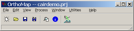
"File" - project management functions (Open, Create, Save):
"New Project" - creates a new project;
"Open Project" - opens an existing project;
“Import points” – imports ground control points (GCP) into project;
"Preview" – you can view any image in supported format;
“Open Map” – this option is available after opening main image in exterior orientation process;
"Save Project" - saves current project;
"Save As" - saves current project with a different name;
"Info" - displays information about project;
"Save Info" - saves information about project in a file;
"Print Info" - prints the information about project on default printer;
"Exit"- exits the program.
"Edit" - project editing, setting project parameters:
"Coordinate System"- opens project window on Output CS page;
"Camera"- opens project window on camera page;
"Topocentric System"- opens project window on topo page;
"Ortho Image Location"- opens project window on AOI location page;
"Resampling Type"- opens project window on Output CS page;
"Define Raw Image";
"Define Ortho Image";
"Define DEM";
"Define Ground Control Points";
"Orientation"
“Window”
“Arrange all windows” - default position for all program windows
"View"
"Preview"– opens Open dialog for selecting preview image;
"Process" - processes of image orientation and transformation;
"Orientation" - image exterior orientation;
"Rectification (Ortho)" - image orthorectification;
"Registration" - image registration without rectification;
"Simple Registration" - image registration only dX, dY.
"Utilities" – menu of different utilities, user can tune this menu
"Orthorectification" – predefined tool for rectification
"Import DEM from XYZ file" – predefined tool for DEM import
"Import DEM from line format" – predefined tool for DEM import
"Import DEM from one Z on line" – predefined tool for DEM import
"Help" - on-line help system.
Creation of a project
After start of the software there are only two
available items in Main Menu/File: "New Project" and
"Open Project". Select "File" form Main Menu,
select "New Project" (or select "New Project"
button ![]() from tools palette). A new project is automatically created, WGS-84/UTM coordinate system is selected by
default with appropriate message in message window. Editing and saving of project become available after
creation of a project.
from tools palette). A new project is automatically created, WGS-84/UTM coordinate system is selected by
default with appropriate message in message window. Editing and saving of project become available after
creation of a project.
Note:
a project is created in RAM. To save it to your hard disk select "Save
Project" or "Save as" from "File" menu (or use
"Save Project" ![]() or "Save as"
or "Save as" ![]() buttons from tools palette).
buttons from tools palette).
Opening an existing project
Select
"Open project" from "File" menu or use "Open
project" ![]() button from tools palette. Common "open file" dialog is
activated. Use this dialog to find and select a project file. Project editing
and saving functions become available after opening a project. Project window
will be automatically opened.
button from tools palette. Common "open file" dialog is
activated. Use this dialog to find and select a project file. Project editing
and saving functions become available after opening a project. Project window
will be automatically opened.
Note:
a project is created in RAM. To save it to your hard disk select "Save
Project" or "Save as" from "File" menu (or use
"Save Project" ![]() or "Save as"
or "Save as" ![]() buttons from tools palette).
buttons from tools palette).
Import ground control points
Ground Control Points (GCP) for project are stored in file with name of project and extention ‘.gcp’ -<projectname>.gcp, format of this file is described in section “Format of GCP file”
You can enter control point manually or define them from raster map in process of exterior orientation.
Or if you have external file of control points in GCP format you can import it into project.
Select "Import points" from "File" menu. Then select required file of gcp format from standard open file dialog.
Preview image
Select "Preview" from "File" menu. Then select required image file from standard open file dialog. It is possible to view files of the following types: *.OSD, *.BMP, *.TIF, *.JPEG, *.ERS, *.DTM. After a file is selected, the preview image window are opened.
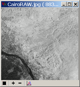
Preview Window
Preview window contains the following buttons:
![]() -
display the whole image in the window;
-
display the whole image in the window;
![]() -
zoom in by 2;
-
zoom in by 2;
![]() -
zoom out by 2;
-
zoom out by 2;
![]() - authomatic histogram stretch
- authomatic histogram stretch
In the title of window X, Y pixel coordinates of an image point are shown.
Obtaining information on active project
To
obtain information on current status of active project select "Info"
from "File" menu or use "Project information" ![]() button from tools palette.
button from tools palette.
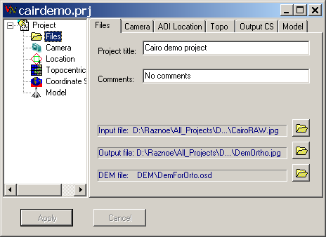
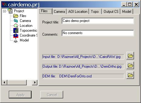
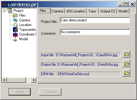
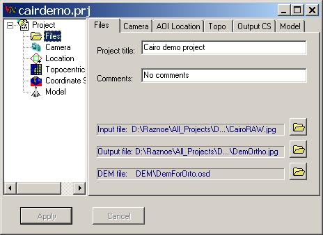
Appearing Information window contains the following pages:
· Files - setting of working files
· Camera - setting of camera parameters
· AOI location - setting of location and size of orthoimage (AOI)
· Topo - setting of topocentric system location
· Output CS - setting of coordinate system and pixel resampling type
· Model - setting camera model
Active project is not automatically saved to your hard disk. If some changes are made to active project, the information window will display them rather than project information stored in the project file on the hard disk. To store the changes in the file, save active project (see Note to the section "Opening an existing project" above).
Editing a project
Setting of working files
Select item "Define Raw Image" from "Edit" menu to define source image file using common "Open file" dialog. Or you can click line “Input file” on page “Files”.
Select item "Define Ortho Image" from "Edit" menu to define name and directory path of output orthoimage file. Or you can click line “Output file” on page “Files”.
Select item "Define DEM" from "Edit" menu to define DEM file name (not used for transformation to mean plane) using common "Open file" dialog, also can be used to remove the DEM from the project. Or you can click line “DEM file” on page “Files”.
On this page you can define Project title and give some Comments for this project.
If you have control points in separate GCP file, then you can import them into project. Select item "Import points" from "File" and select file name using common "Open file" dialog. When you save project, control points will be saved in file with name of project file and ‘.gcp’ extention. The GCP file contains information determining location of each control point on image in pixel coordinates and on the ground in geographic coordinates. GCP file format described in section "Formats of Files".
Setting of camera parameters
Select "Camera" from "Edit" menu. Camera parameters setting window is displayed.
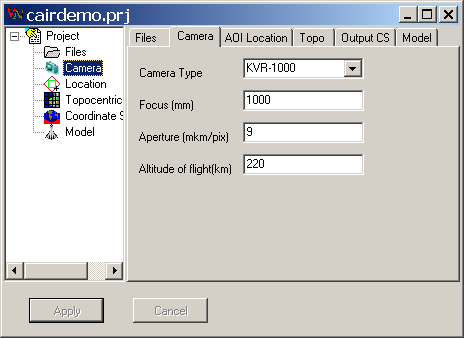
Select camera type from "Camera type" list. Then the parameters "Focus", "Aperture" and "Altitude of flight" are automatically set for selected camera type. Each parameter can be changed separately. For other cameras select camera type "Unknown" then enter the camera parameters manually.
The required parameters are the following:
· Focus - camera focal length (in millimeters);
· Aperture - scanning aperture (in microns per pixel);
· Altitude of flight - average altitude of shooting (in kilometers).
To save the changes in camera parameters, save active project (see Note to the section "Opening an existing project" above). To discard changes press "Cancel" button.
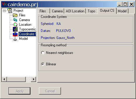
Setting of coordinate system and pixel resampling method
Select "Coordinate system" from "Edit" menu, then select required coordinate system from two available (Gauss-Kruger on Krasovsky spheroid or UTM on WGS-84 spheroid). Or you can simply click on lines “Spheroid”, “Datum”, “Projection” and coordinate system changes.
Select "Resampling type" item from "Edit" menu, then select necessary pixel resampling type from the list. Current resampling type is marked in the list. The best choice for “black and white” imagery is “Bilinear interpolation”, but it can change colours for multispectral (RGB) images. "Nearest neighbour" resampling method is faster and does not change colour of RGB images.
Note. All coordinates in the system are to be specified with zone number as first digits in Easting coordinate.
For example: 12356800 – 12 zone 356800- coordinates in zone
Setting of location and size of orthoimage.
To set location and size of orthoimage select item "Ortho Image Location" from "Edit" menu.
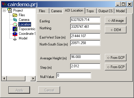
Output orthoimage is oriented along Easting/Northing axes of specified coordinate system, so orthoimage location is determined by one point - North-West corner of orthoimage corresponding to output file coordinates 0:0 (upper left corner of the output image). For transformation of the image to mean plane of the required area average height of the area must be specified.
Attention! Average height is also used for the pixels of the required area beyond DEM area. It may lead to image distortions at the DEM / average height border area if difference in heights is significant. To avoid this, control orthoimage and DEM area sizes carefully.
Orthoimage size and grid step are specified in meters.
To process the whole input image use "All Image" button. In this case the coordinates of North-West corner, output pixel size corresponding to input pixel size and orthoimage size corresponding to the whole input file are determined from the parameters of exterior orientation corresponding to the set of ground control points. These values are used as orthoimage location.
To process the image within DEM borders use "DEM" button.
Use "From GCP" button to define the mean plane with the height determined as average of the heights of control points.
Use "From GCP" button to define the step of output image from ground control points.
A local Cartesian topocentric system is used for production of orthoimage. Using "Calc Topo" button the origin of the topocentric system is located in the center of orthoimage area (the option "Auto topocentric" is automatically turned off). For most tasks this way of location of topocentric system is recommended. An advanced user can specify the location of the topocentric system manually.
Output orthoimage file pixels outside the image area will be filled with "Null Value" (for 8-bit grayscale 0 is black, 255 is white).
Setting of topocentric system location
Topocentric coordinate system is the Cartesian system in which exterior orientation will be done. It can be defined by its origin and azimuth. To set location of topocentric system select "Topocentric System" item from "Edit" menu. Or select page “Topo” of project window.
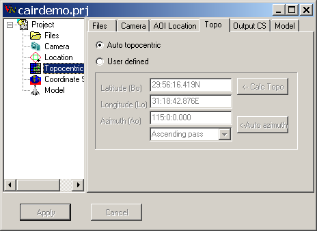
Radio buttons If selected
Auto topocentric Origin of topocentric system defines in the centre of control points (default)
User defined Origin of topocentric system can be defined by user
Button
Calc Topo origin of topocentric system defined in the centre of area of interest (AOI)
Auto Azimuth azimuth of topocentric system sets from camera definition according to the pass of satellite
ComboBox
Ascending pass ascending pass of satellite orbit
Descending pass descending pass of satellite orbit
For most tasks “Auto topocentric” location of topocentric system is recommended. An advanced user can specify the location of the topocentric system manually.
You can specify latitude and longitude of the origin of topocentric system on Topo page of Project window. The coordinates are entered in the following format:
ddd:mm:ss.ss N|S|E|W
where:
ddd - degrees;
mm - minutes;
ss.ss - seconds with decimal fractions;
N|S|E|W - North, South, East, or West.
"Auto Azimuth" button is used for automatic setting of azimuth of the topocentric system according to the camera type and taking into account ascending or descending orbit (option "Ascending pass"):
Camera type KVR-1000 TK-350 KFA-1000,MK-4 LandsatTM AerialPhoto
Ascending orbit 115 25 8 98 0
Descending orbit 245 155 172 98 0
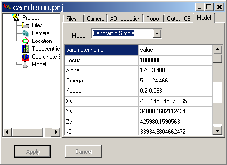
Setting camera model
The source image can be described using various models. There are 7 models for image orientation in OrthoMap:
· Polynomial (Conformal).
· Polynomial (Affine).
· Polynomial second order.
· Frame (central projection);
· Simple Dynamic;
· Panoramic Static;
· Panoramic Dynamic;
You can choose geometric model of image which will be used for external orientation on page “Model” of Project window.
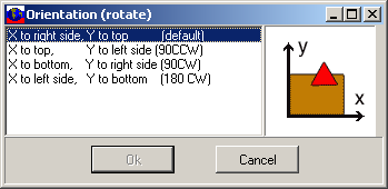
Setting direction of image coordinate system
The source image file has left coordinate system, but to solve the task of orientation it is necessary to use right coordinate system. It is possible to transform left coordinate system to right one in several variants. In OrthoMap it is possible to select the direction of image coordinate system. Select Edit -> Orientation, then select one of the four possible directions of coordinate system in Orientation window.
Exterior orientation image and map windows
You can do
external orientation by pressing “Exterior orientation” ![]() button on main window toolbar.
button on main window toolbar.
Will be opened two windows:
· Exterior orientation – with list of control point (if were imported or defined in previous run) .
· Image window - with input image.
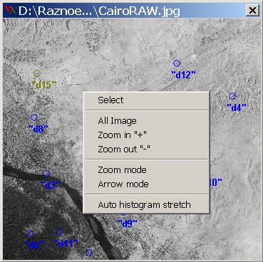
On image window you can use commands:
Select - select conrtol point closest to cursor position;
All image - fit image to window (keyboard grey *);
Zoom in - increase image in window (keyboard grey +);
Zoom out - decrease image in window (keyboard grey -);
Zoom mode - cursor in zoom mode (left click – select in image central point of window,
drag cursor – new zoom);
press key ‘Shift’ and you will be able to change pixel coordinates for current control point
(instant Arrow mode );
Arrow mode - left click changes pixel coordinates for current control point
Auto histogram stretch - increase brightness of image.
All command are available from popup menu (right click on image).
“Open raster
map” ![]() button will be shown on main window toolbar.
button will be shown on main window toolbar.
General description
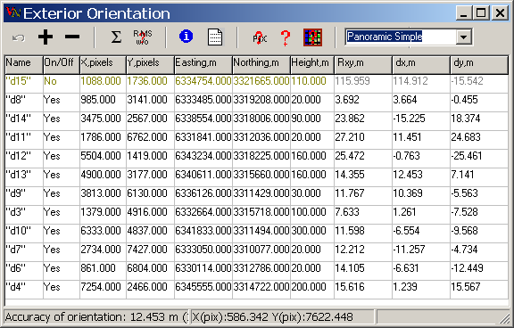
The window "Exterior Orientation" contains the table of GCPs each of which can be in two modes: On/active ("Yes" in column On/Off) and Off/passive ("No" in column On/Off). Switching of modes can be done by left mouse button double click on the cell "On/Off" of the row with required point. Active points will be used in orientation process automatically. Position errors in X and Y will be shown in columns "Rxy,m", "dX,m" and "dY,m". The aggregate result of orientation (RMS) will be shown in status line in the bottom of the window.

The GCP table has the following fields:
· Name - point name (without blanks);
· On/Off - point status, only active points will be used in orientation and pixel calculation;
· X, pixels - pixel values of X coordinate in image file;
· Y, pixels - pixel values of Y coordinate in image file;
· Easting, m - geodetic coordinate West-East in meters;
·
· Northing, m - geodetic coordinate North-South in meters;
· Height, m - point height in meters;
· Rxy,m – RMS on x,y;
· dX,m – X error on point;
· dY,m – Y error on point.
There are the following buttons in this window:
Undo - undo last changes;
Add point - add point after the current one;
Delete point - delete current point;
Solve - solve external orientation according current geometric model;
RMS w/o - RMS is calculated for each point (shown in column "RMS w/o") in assumption that this point is passive. In this mode we can find the worst point (with the minimal value in the column "RMS w/o") and turn it off.
Calc pixels - calculate pixel coordinates for current point with known geodetic coordinates, first order polynomial is used, its coefficients are calculated for all active points, not less than two active points with known pixel and geodetic coordinates are required;
Calc pixels for all “No” points - calculate pixel coordinates for current point with known geodetic coordinates, first order polynomial is used, its coefficients are calculated for all active points, not less than two active points with known pixel and geodetic coordinates are required;
Calc map - calculate geodetic coordinates for current point with known pixel coordinates, first order polynomial is used, its coefficients are calculated for all active points, not less than two active points with known pixel and geodetic coordinates are required.
Geometric model - ComboBox for geometric model selection
Edit existing point
For editing of existing point you must select the row with this point in window "External Orientation". The point becomes current and will be shown in the table and on image in appropriate color.
In normal state the image window is in zoom mode (cursor ). For current point you must find its position on image and holding Shift key (the window mode changes to arrow mode and cursor image will be ) click left mouse button in selected location on image. Pixel coordinates in GCP table will be changed for the current point.
To add a new point press button "Add point".
You can define
point geodetic coordinates from map. Press button ![]() “Open raster map” on main window
toolbar and select raster map with the help of standard “Open dialog” window.
Coordinates of point, selected in map window will be displayed in columns “Easting”
and “Northing”.
“Open raster map” on main window
toolbar and select raster map with the help of standard “Open dialog” window.
Coordinates of point, selected in map window will be displayed in columns “Easting”
and “Northing”.
There are three help modes for user (buttons "Calc Pixels", "Calc Map", "RMS w/o").
- you can calculate approximate pixel coordinates from known geodetic coordinates. This mode is available only after defining of location of two points;
- you can calculate approximate geodetic coordinates from known pixel coordinates. This mode is available only after defining of location of two points. This mode can be helpful for defining geodetic coordinates of some feature on image;
- you can calculate aggregate RMS for each active point in condition that this point is passive (button RMS w/o). If you turn off the point with the minimal value in the field "RMS w/o", then the aggregate orientation RMS will change to this minimal value.
Exterior orientation
The source image can be described using various models. There are 7 models for image orientation in OrthoMap:
· Polynomial (Conformal).
· Polynomial (Affine).
· Polynomial second order.
· Frame (central projection);
· Simple Dynamic;
· Panoramic Static;
· Panoramic Dynamic;
In order to achieve maximal accuracy in orthorectification it is necessary to select the image model correctly. The following table shows default settings of orientation model for different types of cameras (these settings can be changed by operator):
Camera type Orientation type (model)
KVR-1000 Panoramic Dynamic
TK-350 Frame
KFA-1000 Frame
MK-4 Frame
Landsat-TM Panoramic Dynamic
Unknown Frame
The transformation parameters include static (frame image) and dynamic parts. All these parameters are determined during exterior orientation. In case of insufficient amount of control points it is possible to determine only static (frame) image parameters.
The following parameters are determined during exterior orientation:
* coordinates of the point of photography;
* 3 angles of shooting;
* 6 dynamic parameters.
Select "Orientation" item from "Process" menu. If control points file is present, Exterior orientation window is opened.
The window contains a table of control points. Each point can be included into or excluded from the process of orientation by left-clicking in appropriate "On/Off" cell. To start the process of orientation press "Solve" button . Resulting accuracy (RMS error) of orientation is then displayed in "Accuracy of orientation" field. The column "Rxy" in the control points table shows RMS for each point. After completion of the process of orientation the resulting orientation parameters can be viewed in the Information window using "Info" item from "File" menu or "Project information" button from tools palette. It is also possible to store the orientation accuracy report in a file by pressing button. Before starting the process of orthorectification the active project must be saved for the resulting orientation parameters to be stored in the project file.
Rectification
If the accuracy of exterior orientation is acceptable then it is necessary to save the parameters in project file by pressing "Save Project" button.
To start the module of orthorectification with current project select "Rectification (Ortho)" item from "Process" menu. If exterior orientation not solved then module rectify.exe will not start. If project was changed then you will be asked to save project before start of Rectify module.
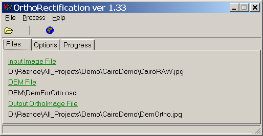
The module works with active project. The module window displays the following information:
· source image file name;
· output file name;
· number of columns and rows of output file;
· grid steps in meters along X and Y axes for output file.
To start the process of orthorectification press "Start" button. Progress indication window displays elapsed processing time, approximate remaining processing time and percentage of process completion. To interrupt the process press "Cancel" button. If DEM is not specified when starting the process, transformation will be performed to mean plane with the height specified in the active project with appropriate message displayed in message window.
Utilities
Initially Menu “Utilities” contains some useful utilities:
"Orthorectification" – predefined tool for rectification
"Import DEM from XYZ file" – predefined tool for DEM import
"Import DEM from line format" – predefined tool for DEM import
"Import DEM from one Z on line" – predefined tool for DEM import
You can tune this menu. Menu items may be defined in file ‘tools.ini’ in OrthoMap folder.
You must fill two lines for every menu item:
first line – CaptionXXX – text line which will be shown in menu;
second line – ModuleXXX – program, loaded on click,
where XXX – number of menu line, first line has number 000.
If CaptionXXX=- then there will be only line in the menu (see line Caption001)
And Number must be equal to overall quantity of menu lines
Example of predefined menu:
[Tools]
Number=5
Caption000=Orthorectification
Module000=rectify.exe
Caption001=-
Module001=-
Caption002=Import DEM from XYZ text file
Module002=Xyz2Bin2.exe
Caption003=Import DEM from line format
Module003=Line2Bin.exe
Caption004=Import DEM from one Z on line
Module004=Asc2Bin.exe
The Coordinate Calculator
Coordinate Calculator may be used for calculation of ground control points in needed projection.
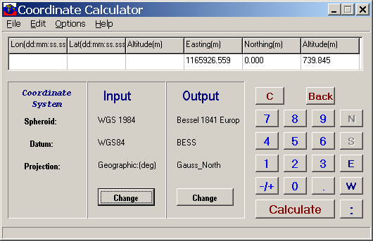
See Coordinate Calculator User’s Guide for detailed description http://vinek.narod.ru/ccalc_ru.html
Reproject Utility
Reproject utility is used to reproject orthoimages and DEM from one coordinate system to another. Input and output coordinate systems are specified in the same way as in Coordinate Calculator (see above section). Specify "Input file" and "Output file" through common "Open file" dialog. It is possible to specify required pixel size in meters for output file (by default it is equal to input file pixel size).
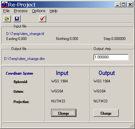
For detailed description see ReProject User’s Guide
Import of DEM from ASCII file
For orthorectification it is necessary to use DEM in OSD format. For this purpose it is possible to import DEM from ASCII files.
ASCII format with one height value per a line, lines are separated by <CR>/<LF>. Beginning of output DEM file in OSD format corresponds to the North-West corner of the area. Therefore, the height values in input ASCII file must start from the North-West corner of the area and be located by lines. The origin point is the North-West corner of DEM. If source ASCII file is recorded starting from the South-West corner, then after import it is possible to use FLIP utility to flip DEM around horizontal axis.
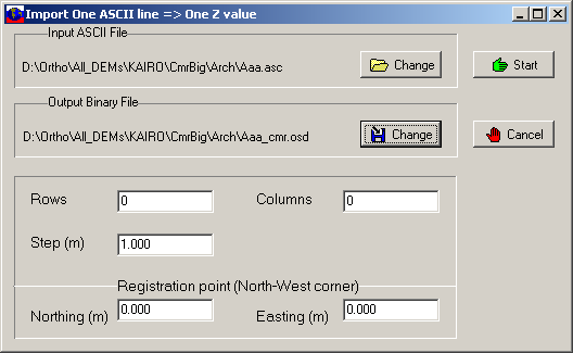
Module ASC2BIN.
Import of DEM from ASCII file
· ASCII format with each line containing all height values of DEM in one line. The values are blank separated, lines are separated by <CR>/<LF>. The order of input lines must corrspond to North-to-South direction. The origin point is the North-West corner of DEM.
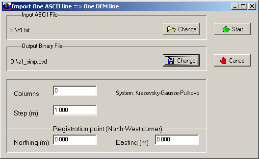
Module Line2BIN.
Import of DEM from ASCII file
* ASCII format with values X (Easting), Y (Northing), Z (Height) in each line, lines are separated by <CR>/<LF>. X, Y, Z values must be blank separated. X, Y, Z values can be preceded by a point number, in this case it is necessary to specify option "ignore first column". Input file must contain all X, Y, Z values of a regular matrix. Interpolation of missed heights is not performed. If a value is missed, the DEM element is filled with a default value (0).
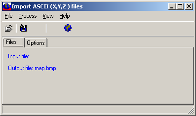
Module XYZ2BIN.
Export of DEM to ASCII file
If necessary it is possible to export DEM from the interior format OSD to ASCII file in one of the following formats:
* ASCII format with one height value per a line, lines are separated by <CR>/<LF>. The hight values in output file are located from the North-West corner by lines.
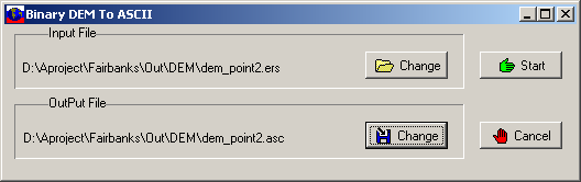
Module BIN2ASC.
* ASCII format with each line containing all height values of DEM in one line. The values are blank separated, lines are separated by <CR>/<LF>. The hight values in output file are located from the North-West corner.
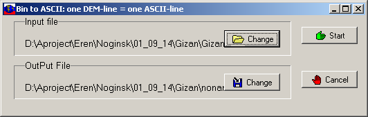
Module BIN2Line.
ASCII format with values N (point number), X (Easting), Y (Northing), Z (Height) in each line, lines are separated by <CR>/<LF>. N X, Y, Z values are separated by comma and blank. The points in output file are located from the South-West corner by lines.
Module BIN2XYZ.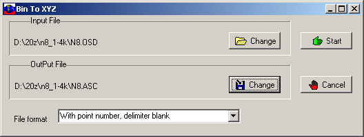
Flip
To flip or rotate source image and DEM files around horizontal axis use "Flip" utility from "Utilities" item of Main Menu.
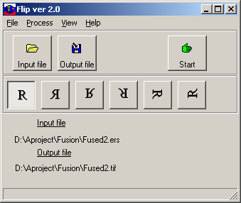
- no flip, can be used for format conversion, e.g. TIFF to BMP;
- flip around vertical axis;
- flip around horizontal axis;
- rotation 1800;
- rotation 900 clockwise;
- rotation 900 counterclockwise;
Formats of input files
· Source imagery. Source image may be in TIFF, BMP, JPEG, OSD, ERS, DTM format.
· DEM files. DEM must be in OSD, ERS, DTM or TIFF 16-bit format or can be imported from ASCII format (see "Import of DEM from ASCII file" above).
Format of output orthoimage
Images can be saved in TIFF, BMP, JPEG, OSD(OrthoMap Dataset), ERS formats. In OSD format the image or DEM data is stored in BIL format starting from the upper left corner of image or DEM. Accompanying information (geo information, image size, etc.) is stored in a separate text file (header) with the same name as the data file and extension OSD. The data file name has no extension.
For TIFF, BMP and JPEG formats corresponding geo-referencing file ("world file") is automatically created, e.g. TFW for TIF.
Format of OSD file header
OSD header is divided into the following blocks of information:
CoordinateSystem. This block contains the following:
Ellipsoid ("Datum");
Cartographic projection ("Projection");
Units of measurement ("Units") - meters.
ImageInfo. This block contains the following:
* Cell type ("CellType");
* X and Y cell sizes in "Units" (XDimension, YDimension);
* Number of lines ("NrOfLines") and columns ("NrOfCellsPerLine") of the data file;
* Geodetic origin point ("RegistrationPoint") - geodetic coordinates of the geodetic reference point are specified in "Units";
* Pixel coordinates of the geodetic reference point in data file ("RegistrationCellX" and "RegistrationCellY");
Number of bands ("NrOfBands").
Example
OrthoSetDataHeader [
Version = 1.0
LastUpdated = Fri Jun 30 17:20:24 GMT 2000
DataSetType = OrthoSetData
ByteOrder = LSBFirst
CoordinateSystem [
Datum = "PULKOVO"
Projection = "GAUSE15"
Spheroid = ""
Units = "METERS"
CoordinateType = EN
CoordinateSystem ]
ImageInfo [
CellType = UNSIGNED16BITINTEGER
Xdimension = 20.000
Ydimension = 20.000
NrOfLines = 250
NrOfCellsPerLine = 250
RegistrationPoint [
Eastings = 6334000.000
Northings = 3324000.000
RegistrationPoint ]
RegistrationCellX = 0.000
RegistrationCellY = 0.000
NrOfBands = 1
ImageInfo ]
OrthoSetDataHeader ]
Format of GCP-file
Ground Control Points (GCP) file is created by View and Measure (V&M) module and is intended for solving the task of exterior orientation. The file is a text file each line of which contains information about one control point in the following format:
<Name> <On/Off> <CellX> <CellY> <GeoX> <GeoY> <GeoZ>
where:
"Name" is point's name;
"On/Off" specifies whether a point is included to the process of orientation ("On") or not ("Off");
"CellX", "CellY" are file pixel coordinates of a point;
"GeoX", "GeoY" are accordingly Easting and Northing coordinates of a point in meters in selected cartographic projection;
"GeoZ" is height of a point in meters.
Example:
Name On/Off CellX CellY GeoX GeoY GeoZ
6_3 Yes 11623.500 3001.500 8224924.070 2019273.800 2713.240
6_4 Yes 11756.500 3533.500 8228258.370 2019053.460 2636.130
7_4 Yes 11165.500 3923.500 8229381.510 2014885.680 2520.240
7_5 Yes 11404.500 4533.500 8233366.060 2015145.070 2392.550
7_6 Yes 11535.500 5296.500 8238031.170 2014480.110 2251.360
8_4 Yes 10516.500 3920.500 8228202.040 2011003.240 2789.130
8_5 Yes 10892.500 5201.500 8236113.530 2011195.720 1477.380
8_6 Yes 10562.500 5665.500 8238150.650 2008438.600 1290.270
8_9 Yes 11582.500 8136.500 8254624.010 2009277.840 2137.370
9_9 Yes 10879.500 8344.500 8254497.070 2004745.150 2194.620
7_7 Yes 11845.500 6690.500 8246715.120 2013603.510 2197.420
Format of PTS file - control points
<point name> <X coordinate Easting> <Y coordinate Northing> <height>
Delimiter: blank.
Example:
Point name X coordinate Easting Y coordinate Northing Height
6_3 8224924.070 2019273.800 2713.240
6_4 8228258.370 2019053.460 2636.130
7_4 8229381.510 2014885.680 2520.240
7_5 8233366.060 2015145.070 2392.550
7_6 8238031.170 2014480.110 2251.360
8_4 8228202.040 2011003.240 2789.130
8_5 8236113.530 2011195.720 1477.380
8_6 8238150.650 2008438.600 1290.270
8_9 8254624.010 2009277.840 2137.370
9_9 8254497.070 2004745.150 2194.620
7_7 8246715.120 2013603.510 2197.420
OrthoMap abnormal termination error codes
1 ERROR_INVALID_FUNCTION
2 ERROR_FILE_NOT_FOUND
3 ERROR_PATH_NOT_FOUND
4 ERROR_TOO_MANY_OPEN_FILES
5 ERROR_ACCESS_DENIED
6 ERROR_INVALID_HANDLE
7 ERROR_ARENA_TRASHED
8 ERROR_NOT_ENOUGH_MEMORY
9 ERROR_INVALID_BLOCK
10 ERROR_BAD_ENVIRONMENT
11 ERROR_BAD_FORMAT
12 ERROR_INVALID_ACCESS
13 ERROR_INVALID_DATA
14 ERROR_OUTOFMEMORY
15 ERROR_INVALID_DRIVE
16 ERROR_CURRENT_DIRECTORY
17 ERROR_NOT_SAME_DEVICE
18 ERROR_NO_MORE_FILES
19 ERROR_WRITE_PROTECT
20 ERROR_BAD_UNIT
21 ERROR_NOT_READY
22 ERROR_BAD_COMMAND
23 ERROR_CRC
24 ERROR_BAD_LENGTH
25 ERROR_SEEK
26 ERROR_NOT_DOS_DISK
27 ERROR_SECTOR_NOT_FOUND
28 ERROR_OUT_OF_PAPER
29 ERROR_WRITE_FAULT
31 ERROR_GEN_FAILURE
32 ERROR_SHARING_VIOLATION
33 ERROR_LOCK_VIOLATION
34 ERROR_WRONG_DISK
36 ERROR_SHARING_BUFFER_EXCEEDED
38 ERROR_HANDLE_EOF
39 ERROR_HANDLE_DISK_FULL
50 ERROR_NOT_SUPPORTED
51 ERROR_REM_NOT_LIST
52 ERROR_DUP_NAME
53 ERROR_BAD_NETPATH
54 ERROR_NETWORK_BUSY
55 ERROR_DEV_NOT_EXIST
Technical support
Home Page: http://vinek.narod.ru
E-mail: vinek@list.ru